


A significant component
of a spacecraft or aircraft is the landing gear, also referred to as the
undercarriage. The gear is a formation that holds the plane on the surface and
enables it to take-off, land, and taxi (Federal Aviation Administration, 2012).
The design of the landing gear is likely to pose several interferences to the
structural design of the aircraft. Boeing 777 encompasses several design
parameters that strongly influence the plane’s aerodynamics and configuration
design. The aircraft's landing gear forms the leading ever built-in into a
commercial aircraft to date. The gear has various important aspects, such as
retraction mechanism, brakes, and shock absorber (Komorowski, 2011).
Accordingly, the following entry endeavors at discussing Boeing 777 landing
gear system while highlighting how it operates.
Constituent Parts of Boeing 777 Landing Gear System
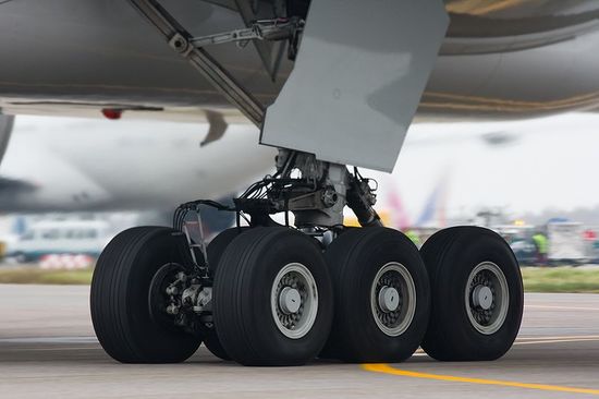
The landing gear for
Boeing 777 embraces a typical two-post configuration containing one nose gear
and two main landing gears. As compared to the traditional four-wheel units,
each of the two gears of the plane consists of six wheels in parallel pairs.
The arrangement provides the main landing gear with twelve wheels whose role is
better weight distribution on taxi areas and runways as well as avoidance of
the necessity for an extra two-wheel gear beneath the hub of the fuselage.
Likewise, the six-wheel pattern allows for a more cost-effective brake design
(Moaveni, 2011).
Boeing 777’s aft hinges of every main gear are steerable to enhance the turning radius. The hydraulic system at the center supplies hydraulic power for extension, retraction, and steering. While the hydraulic system on the right side powers the regular pedal hydraulic system, the one at the center powers the reverse or alternate pedal hydraulic system. However, both systems provide antiskid protection, but only the regular system provides the auto brake system. Moreover, the tire pressure indicator and the brake temperature examiner display the tire pressure and the brake temperature on the synoptic display of the gear. While the nose wheels do not have brakes, each of the main gear wheels comprises of multiple disc carbon brakes. The brake structure encompasses of normal brake, parking brake, antiskid protection, reserve or alternate brake, auto brake system, and brake accumulator (Mallick, 2007).
Main Landing Gear
The main landing gear
bar contains an air-oil buffer. A side brace and a drag brace are responsible
for transmitting weight from the strut to the plane structure. When the gear is
completely extended, over-center techniques shut both braces. During gear extension
and retraction, the gear doors on the main gear wheels open and close. The
aircraft’s truck encompasses of three axles. At their ends, the axles harbor a
wheel-tire and a brake assembly. The rear axle spins around to steer the main
gear (Federal Aviation Administration, 2012).
Normal Operation
The principal landing
gear utilizes the hydraulic pressure, originating from the central system, to
extend and retract. Sequence valves assume the task of controlling
the gear and door movement. Side brace and drag brace down lock activators then
lock the gear within the broadened position. Sequentially, uplock hooks bolt
the gear within the retracted location. The trucks of the principal landing
gear tilt at about 130 forward tires up extending the gear. The trucks of the gear
tilt at approximately 50 forward tires down, with the gear in transit or up and
locked (Moir & Seabridge, 2011).
Alternate Extension
Alternate
extension mechanism employs a dedicated direct current electric hydraulic pump
as well as interior hydraulic system liquid for extension of the landing gear.
The structure allows for landing gear extension when the core hydraulic system
does not have pressure. The alternate extend power pack provides hydraulic
pressure that unlocks the landing gear and its doors. Consequently, the gear
extends and the doors open using their own weight. After the alternate
extension, the gear doors remain open.
When the alternate gear
button reads DOWN, the gear uplocks and all doors are released. The landing
gear falls freely to the secured position. Nonetheless, the landing gear switch
does not influence the alternate extension. Upon using the alternate extension,
the position indication on EICAS landing gear portrays the position indication
of the expanded gear. Throughout alternate extension, EICAS displays the text
GEAR DOOR each of the hydraulically powered door is open. Subsequent to an
alternate extension, it can be possible to retract the landing gear via the
normal technique if it is working. This can be done by selecting DN before
selecting UP (Federal Aviation Administration, 2012).
Ground Door Operation
The alternate extension
technique permits one to unbolt the doors when the plane is on the surface. The
hydraulic pressure at the core of the system locks the doors.
Nose Landing Gear
This gear strut embraces
an air-oil buffer. A folding drag strut transmits weight from the brace to the
aircraft structure. When the nose gear is completely retracted or extended, the
over-center system of the lock fastens the drag strut. During gear extension
and retraction, the nose gear’s forward doors operate hydraulically while the
rear doors operate through mechanical links that are attached to the nose gear
(Erikson & Steenhuis, 2015).
Normal Operation
To facilitate in extension
and retraction, the nose landing gear employs hydraulic pressure from the
center system. The sequence valves assume the role of controlling landing gear
and forward movement (Erikson & Steenhuis, 2015).
Alternate Door Extension
Alternate extension for
the nose gear employs hydraulic pressure emerging from the alternate-extend
power pack. The land gear and the forward doors use their own weight to extend
and open respectively. After alternate extensions, the forward doors do not
shut (Erikson & Steenhuis, 2015).
Ground Door Operation
The alternate extension
mechanism allows for opening the anterior doors when the plane is on the
surface. The frontal doors unfasten using their own weight. However, they shut
using the hydraulic pressure emerging from the core system (Erikson &
Steenhuis, 2015).
Landing Gear Operation
The landing gear switch
is responsible for controlling the landing gear. On the surface, an automatic
lock holds the switch in the DN location. The lock can be physically overridden
via pressing and clasping the landing gear override switch. During flight, the
switch lock is mechanically let loose through ground or air sensing (Erikson
& Steenhuis, 2015).
Landing Gear Retraction
Retraction of the
landing gear takes place when the lever moves up. The gear doors unlock and the
wheels of the main gear tilt, assuming a retract position. As the gear retracts
into the tire wells, the position of the EICAS (Engine Indicating and Crew
Alerting System) landing gear assumes a white crosshatch signal from a green
down signal (Federal Aviation Administration, 2012). After retraction, the
uplocks hold the landing gear. Accordingly, the EICAS gear location display
adjusts to UP for ten seconds before blanking. With all doors locked and the
landing gear pulled in, the hydraulic system depressurizes automatically. In
case the standard transit time elapses and a gear is not locked up, the EICAS
displays a caution message. Further, the gear position indicator on the EICAS
changes to an expanded informal format while the affected gear is displayed as
down or in-transit.
Landing Gear Extension
Once the landing gear
switch moves to DN, the doors affiliated to the landing gears open, the gear
unlocks, and the in-transit signal displays on the EICAS indication. The gear
falls freely to the down, locked position without application of hydraulic
power. Then, down locks are powered towards the locked point, the key gear
trucks incline hydraulically toward the flight position, and the hydraulically
activated doors lock. After all gears are secure, the EICAS gear signal
displays DOWN. However, if one of the gears is not safely locked, the EICAS
displays a caution message saying ‘GEAR DISAGREE’ after the standard transit
time. Subsequently, the EICAS signal assumes an expanded non-formal layout,
displaying the affected gear as in-transit. If only a single strut on a key
gear is bolted after the standard transit time, a caution message for the
concerned gear displays on the EICAS. If a hydraulically activated door does
not close after the average transit period, the EICAS displays an advisory
message reading ‘GEAR DOOR’ (Moaveni, 2011).
Main Gear and Nose Wheel Aft Axle Steering
Boeing 777 is fitted
with both main gear and nose wheel rear axle steering (Federal Aviation
Administration, 2012). While the reserve hydraulic system has been used to
power nose wheel steering, the center hydraulic system has been used to power
main gear rear axle steering. A nose wheel navigation rudder for every pilot
proves vital in providing prime steering control. On the other hand, rudder
pedals offer minimal steering control. The rudders are capable of tilting the
nose wheels to a maximum of 700 in any direction. They contain pointers on
their assembly that show their position in relation to their neutral location.
The tiller pedals may be used in turning the nose wheels to a limit of 70 in any direction.
Main gear rear axle steering assumes operation automatically when the angle of
the nose wheel navigator exceeds 130 with the aim of reducing tire scrubbing.
In case the main gear rear axles fail to lock during takeoff, a warning message
displays on the EICAS, along with a takeoff configuration acoustic alert.
Similarly, in case the main gear navigation activators are not locked into the
central position when a command authorizes so, the EICAS displays an advisory
message (Moaveni, 2011).
Landing
During landing, the
pilot can choose five levels of reducing speed. However, on dry landing strips,
the highest autobrake deceleration speed is less than the one produced by
complete pedal braking. Subsequent to landing, autobrake use begins when the
wheels spun up and thrust switches have retarded to inoperative. Autobrake use
takes place shortly after main gear comes to rest. If the pilot selects MAX
AUTO, he limits deceleration to the level of autobrake 4 until pitch position
rotates to less than 10, then deceleration increases to the level of MAX AUTO. The extent
of deceleration can be altered without deactivating the system via revolving
the selector. Autobrake pressure can be minimized to sustain the chosen plane
deceleration rate. Ultimately, the system offers complete braking until the
plane comes to a halt or the system is deactivated (Erikson & Steenhuis,
2015).
The Boeing 777 landing
gear system is renowned for performing flawlessly. The unique gear system
allows aircrafts to rotate early through changing the rotation focal point from
the main axis to the rear axle. As the plane revolves, the nose manages to rise
higher. The features of the landing gear allow the plane to take off on short
runways.
References
Erikson, S. &
Steenhuis, H. (2015). The global commercial aviation industry.
Oxon, OX: Routledge.
Federal Aviation
Administration (2012). Aviation maintenance technician handbook-
airframe volume 2. New York, NY: AMT Exams.
Federal Aviation
Administration (2012). Federal aviation regulations/ aeronautical
information manual 2013. New York, NY: Skyhorse Publishing Inc.
Komorowski, J.
(2011). ICAF 2011 structural integrity: influence of efficiency and
green imperatives: Proceedings of the 26th symposium of the
international committee on aeronautical fatigue, Montreal, Canada, 1-3 June
2011. Canada, CA: Springer
Science & Business Media.
Mallick, P.K.
(2007). Fiber-reinforced composites: materials, manufacturing, and
design, 3rd edition. Boca Raton, FL: CRC Press.
Moaveni, S.
(2011). Engineering fundamentals: an introduction to engineering SI
edition. Stamford, CT: Cengage Learning.
Moir, I. & Seabridge,
A. (2011). Aircraft systems: mechanical, electrical and avionics
subsystems integration. New York, NY: John Wiley & Sons.
Additional articles
12 Company Analysis: Team-building Activities thatPromote Cohesiveness and Productivity​Experts recommend that group activities should promote happiness, communication, and team bonding. According to Smart&nb...Team-building-Activities-for-Cohesiveness-and-Productivity:-A-Company-Analysis …
Read ArticleWe all know how hard it is to find the right balance between school work and other aspects of life. At the very least, you need to sacrifice your social life to have a successful academic career. Add to that the fact that you also have to ke...6-Facts-Everyone-Should-Know-about-Professional-Essay-Writers …
Read ArticleThe HIH collapse raised several issues with regard to Auditor Independence Introduction HIH Insurance was first listed on the Australian Stock Exchange in 1992 under the cat...The-HIH-Insurance- …
Read Article